
Building a Pwnagotchi with the Waveshare 2.13in display version 3
Alex Dexter
The pwnagotchi is a fun and relatively inexpensive introductory Raspberry Pi0W project for new hackers looking to test their soldering skills and work with basic hardware and networking concepts. Although many tutorials exist for building a pwnagotchi, none that I found worked for the Waveshare 2.13inch display v3, Waveshare’s current version. So, I decided to develop this tutorial and compile all my research for the build in a single place.
Pwnagotchis “eat” Wi-Fi handshakes and “look for stimulation” by discovering new Wi-Fi networks. The pwnagotchi displays an assortment of faces that have different expressions to show its mood. Pwnagotchis can also be used as a basic Wi-Fi penetration testing platform or as a reason to get out and explore the neighborhood for Wi-Fi networks. In this tutorial, we will cover how to build and start your own pwnagotchi using the Waveshare 2.13in E-Ink display HAT version 3.
Tutorial:
In this tutorial, I will be using an image from an independent GitHub. It is important to use this image instead of the image found on the pwnagotchi site because that one is not compatible with the Waveshare version 3 display.
Requirements:
The following parts, tools, and experience are required to for this tutorial:
Parts
Raspberry Pi0W
Waveshare 2.13in E-Ink display HAT version 3 Black and White
Micro-USB to USB cable capable of supporting data transfer
External power bank
Micro SD card with minimum 8 GB capacity (32GB suggested)
Raspberry Pi0W male pin headers (if pins are not pre-soldered)
63-57 rosin core tin lead solder (if pins are not pre-soldered)
Non-solder breadboard (if pins are not pre-soldered)
Wet sponge (if pins are not pre-soldered)
Pi0W case that fits display (suggested)
Velcro tape (suggested)
Tools
Micro SD card reader/writer
Soldering iron (if pins are not pre-soldered)
Computer with USB ports
Software
Raspberry Pi Imager
GitHub version 3 Release
Basic text editor
An SSH client
Knowledge prerequisites:
Basic knowledge of SSH and assigning IP addresses to networking interfaces on your operating system
Ability to write images to SD Cards
Basic knowledge of soldering is also required if the Raspberry Pi model purchased does not have the male pin headers pre-soldered on
Steps:
(1.) Acquire all the parts and tools necessary in a clean, well-lit workspace.
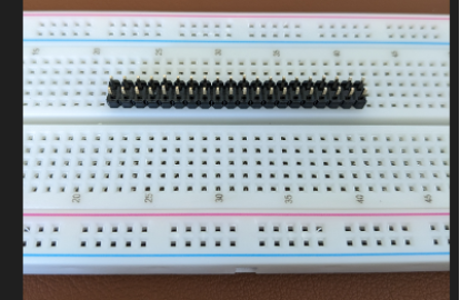
(2.) Place the long end of the male pin headers down into the non-solder breadboard in the two rows closest to the center. If you have purchased a Pi with the pins pre-soldered, you may skip to step 19.
(3.) Place the Pi0W upside down with the short end of the male headers sticking through the GPIO holes. The board should sit flat on the plastic divider.

(4.) Turn the soldering iron to 380 degrees Celsius and allow the iron to heat up.
(5.) Wet the sponge and place it near to the iron.
(6.) Apply a small amount of solder to the tip of the iron. The solder should melt instantly.
(7.) Twist the iron back and forth till the tip of the iron is lightly coated with solder.

(8.) Rub the tip of the iron on the sponge briefly to remove excess solder.
(9.) Starting on the left-hand side of the board and the row of pins farthest from the edge, heat the pin and corresponding copper pad for about a second with the iron.

(10.) Place the end of the solder wire on the heated pin and pad. It should melt almost immediately and from a small but even hill around the pin.
(11.) Remove the soldering iron from the pin and rub any excess solder off from the soldering iron.
(12.) Check the board to make sure it is still lying flat on the pins. If it is not, heat the solder with the iron again and reposition the board so it is sitting flat.
(13.) Once the board is sitting flat, solder the pin to the far left of the board in the row closest to the edge of the board. Make sure the solder on each of the two pins does not touch.
(14.) Solder the remaining pins going from left to right of the board starting with the row farthest from the edge and then moving to the row nearest to the edge. Pause soldering after every two pins and see if the Pi is cool to the touch. Overheating the board can damage the components.
(15.) Once all the pins are soldered, make sure none of the pins are bridged (i.e., have solder from one pin touching solder on another pin).
(16.) Turn off the soldering iron when done.
(17.) Remove the Pi0W from the breadboard. It should look like the picture below.

(18.) Next, place the female pin headers on the e-ink display on the long end of the male pin headers so that the display is covering most of the Pi0W and so that each of the female pin headers matches up with the male pin headers.

(19.) Download and extract the files found at https://github.com/DrSchottky/pwnagotchi/releases/download/v1.5.6-beta2/pwnagotchi-raspberrypi-os-lite-v1.5.6-beta2.zip. It is important to use this image because the official pwnagotchi does not support the Waveshare version 3 display.
(20.) Using the computer, image the SD card with the pwnagotchi-raspberrypi-os-lite-v1.5.6-beta2.img file.
(21.) Using a text editor, create a file named config.toml and save the file to the 256MB Fat32 boot partition of the SD card. Do not save the file to the rootfs partition.
(22.) Enter in the following text. Make sure to make the following changes:
change the main.name field to a name of your choice
change main.whitelist list to include your home SSID
change main.plugins.grid.exclude list to also include your SSID
main.name = "PwnagotchiName"
main.lang = "en"
main.whitelist = [
  "MyWi-Fi"
]

main.plugins.grid.enabled = true
main.plugins.grid.report = true
main.plugins.grid.exclude = [
  "MyWi-Fi"
]

ui.display.enabled = true
ui.display.type = "waveshare_3"
ui.display.color = "black"
(23.) Save the file, then put the SD card into the Pi0W.
(24.) Connect the Pi0W to the computer using the data port as shown below. The data port will power on the Pi0W and begin the first boot configuration.

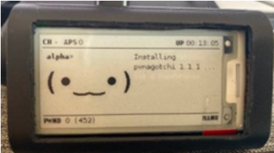
(25.) After connecting the Pi0W to the computer, wait about ten minutes for the Pi to configure. During this time, the Pi will be generating some RSA keys so disconnecting the Pi can corrupt the SD card image (see steps 26-27).
(26.) Disconnect the Pi from the computer, and then reconnect the Pi to the computer using the data port. The Pi0W will power on and the display screen will show that the pwnagotchi has entered Manual mode, indicated by the MANU displayed in the lower right-hand corner.

(27.) Once the Pi is reconnected, a new USB networking interface should appear on the computer. If a new interface does not appear, either the cable that is being used does not support data transfer or the SD card image has become corrupted during setup. First, try connecting a different cable to see if the network interface becomes available. If the computer is still not showing a new network interface, go back to step 21 and try imaging the SD card again.
(28.) Assign the new network interface an IP address of 10.0.0.1, a net mask of 255.255.255.0, a default gateway of 10.0.0.1, and a default DNS of 8.8.8.8 if a DNS address is required. If your home network already uses the 10 address space, it may be easiest to disconnect your computer from the network during setup.
(29.) Using an SSH client, SSH to 10.0.0.2 using the default username “pi” and default password “raspberry”.
(30.) Update the password on the Pi to a new custom password.
(31.) Disconnect the Pi from the computer.
(32.) Connect the Pi to the external power bank using the power port, as shown below.

(33.) After a few seconds, the display should power on, with the word AUTO appearing in the lower left-hand corner of the display.
(34.) The pwnagotchi should now be finished and will begin collecting Wi-Fi handshakes for as long as it is powered on.
If you found this article useful, you may be interested in working with us on your hardware projects.
Tips:
I recommend that once you finish your pwnagotchi, you purchase a case for the device to protect against accidental shorts. If the pins on the pwnagotchi are shorted, the Pi0W will be damaged. Mine is in a case with a piece of Velcro tape on the bottom that allows me to easily connect and disconnect the power bank to the case.
To collect the captured handshakes, you can reconnect the pwnagotchi to your computer through the data micro-USB port and then SSH back into the device after assigning the IP address, gateway, and netmask as before. All captured handshakes are saved in the /root/handshakes directory.
Conclusion:
The pwnagotchi’s versatile functionality makes it a fun tool for basic Wi-Fi penetration tests (notes and information on additional functionality can be found at https://pwnagotchi.ai). There are many methods of building a pwnagotchi, but based on some research, I found my method to be one of the easiest that works with the Waveshare version 3 screen. It also makes for one of the smallest form factors that still has a screen for the pwnagotchi. Best of all, this fun simple Raspberry Pi project can be completed in just a few hours and allows builders to practice basic soldering, networking, and hardware skills.
Sources:
DrSchottky. “Drschottky/Pwnagotchi: (⌐■_■) - Deep Reinforcement Learning Instrumenting Bettercap for WIFI Pwning.” GitHub, https://github.com/DrSchottky/pwnagotchi/.
“Deep Reinforcement Learning Instrumenting Bettercap for WIFI Pwning.” Pwnagotchi, https://pwnagotchi.ai/.
Author: Alex Dexter