
“UEFI is the New BIOS”: Lab Setup
UEFI Reverse Engineering, Vulnerability Discovery and Exploit Development: Part 2
Welcome back to the LSG blog series “UEFI is the new BIOS.” In this installment, we’re going to walk through setting up a UEFI testing lab for reverse engineering and exploit development.
Let’s get started.
Introduction
I have structured this blog post for security researchers looking to learn more about UEFI/BIOS reverse engineering and exploit development. Thus, this lab setup guide covers the bare bones essentials needed to get started with these goals in mind. This post does not cover custom lab builds for specific UEFI testing targets (e.g., exploring PCI-E and DMA attacks). For further learning and details on different UEFI lab testing setups, consult references 1-4 in the References section at the end of this post.
UEFI testing at Leviathan Security Group (LSG) encompasses a broad range of methodologies, spanning hardware-focused, software-focused, and hybrid techniques.
When approaching a new UEFI target for testing and analysis, we consider a few key points to narrow the scope of focus among our myriad testing techniques:
Hardware vs. software targets: Is the focus of the engagement on testing the UEFI security of physical devices (e.g., servers, NUCs, IoT devices), the firmware itself, communication protocols used for onboard intra-component communication and inter-device communication on a network, or some combination thereof? Do we have access to a physical device for testing, and if so, how many? In engagements where no hardware devices are provided or in scope, we utilize software-based approaches, such as reverse engineering with a disassembler/decompiler like IDA Pro and emulation with tools like QEMU. Knowing first and foremost what we are going to test dictates the way we set up our UEFI lab to accomplish those testing tasks in the most efficient way.
Availability of resources: “Resources” here encompasses both physical resources (e.g., hardware tools, number of physical test devices) and non-physical/non-material resources (e.g., time, labor). In any time-boxed testing engagement, the limited time inevitably dictates which tests to prioritize.
Scope: Here, we are solving the equation that maximizes our reach with respect to both depth and breadth of coverage for a given UEFI testing engagement. We find the most elegant way to satisfy the base cases (all required testing activities for a given target) and hit the upper limit of our creativity. For example, a UEFI-focused engagement might be limited to reverse engineering of a specific UEFI firmware image, or it could be expansive and seek to both find UEFI vulnerabilities and demonstrate their impact by developing a complete exploit chain for a target device. The possibilities are (almost) endless (see point 2 above).
These three questions—What is the target? What tools are available? What is the scope? —are essential not just in developing a plan for testing, but in guiding the testing.
These questions will also guide you in developing a lab for UEFI testing.
UEFI Lab: Software Essentials
UEFITool, UEFIExtract, and UEFIFind: Download a release binary of each tool (note that the UEFITool GitHub repo contains all three).
Chipsec loaded onto a USB: Follow this guide.
A hex editor: Dealer’s choice.
A disassembler/decompiler of choice: I primarily use IDA Pro because of the efiXplorer plugin . Other options include Ghidra and Binary Ninja, both of which have UEFI plugins useful for performing various UEFI-specific RE tasks.
fwhunt and fwhunt-scan: fwhunt-scan is an open-source tool from Binarly that leverages their open-source fwhunt vulnerability database in performing static analysis to detect vulnerabilities in a given target UEFI firmware image. It also has a handy extraction utility that can be particularly helpful if you’re encountering difficulties extracting modules from a custom UEFI image using UEFITool (this occasionally happens when custom builds have slightly wonky file formats).
Tianocore’s EDKII: EDKII is an open-source UEFI reference implementation that originally grew out of Intel’s work on the Tiano project, now maintained as a TianoCore community project. It’s supported by engineers both from large companies, like Intel and Apple, as well as engineers in the broader open-source community.
UEFI Lab: Hardware Essentials
TTL-to-USB Serial adapter or DB9-serial adapter for connecting to a serial console on the target device.
A SPI-flash programmer: Used for dumping the flash, reflashing the device with modified firmware, etc. Lately, I’ve been really enjoying using the Hydrabus; it’s a multi-use tool that speaks a myriad of different communication protocols and has open-source, actively-maintained firmware along with a nice little console app. Multi-use tools like the Hydrabus are also great because they expand the range of testing techniques you can employ for finding vulnerabilities and building exploits.
Logic analyzer: I like the Saleae Logic Pro 8. Note: A logic analyzer is not necessary for most types of typical UEFI testing, but it’s an essential tool for a hardware lab. It can be useful for specific types of platform firmware vulnerability research and exploit development. The good news for researchers on a budget: A logic analyzer isn't mandatory. You can absolutely master this topic without investing in expensive hardware like a Saleae (and there are other good logic analyzers for a range of budgets).
UEFI Lab Setup and Diving into Testing
UEFI testing encompasses skills essential in both hardware hacking and low-level systems security. If you’re testing on a physical device, then the first goal is firmware acquisition of the device’s UEFI BIOS, meaning you’ll need to dump the device’s SPI flash. Frequently, you can obtain the UEFI BIOS for a target device directly through the vendor website, although this is not always the case (e.g., unreleased or custom builds). During an engagement, our clients sometimes provide us with this UEFI BIOS. In any case, the goal is to extract the UEFI BIOS firmware from the device’s flash. This allows you to diff the binary with any other versions you’ve acquired/been provided with. (As any seasoned consultant knows, all physical testing tasks – such as UEFI BIOS firmware acquisition – should only be performed on hardware you own or are authorized to test.) Identifying discrepancies between firmware images provides interesting threads to follow and potentially find bugs.
Testing Task #1: UEFI BIOS Firmware Acquisition
Now that your UEFI Testing lab is built, here is the workflow overview of the essential first testing tasks you will perform. To start, set up a serial console and interact with the device during boot. Here, you’re exploring the environment and understanding existing capabilities for user interaction with the pre-boot environment. By default, many systems set Esc as the hotkey to enter the pre-boot console. Other common hotkeys are F2 and F9. Or simply watch the screen during power up and a message will appear, such as, “To interrupt normal startup, press [key]”. Once you press the hotkey, you’ll land in the pre-boot environment. On most production devices, this is a vendor-specific UEFI application (provided by IBVs like Insyde or AMI) that typically presents a Management/Administration console with a GUI.
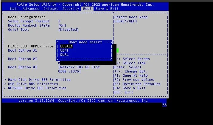
Figure 1: AMI Aptio Setup Utility for UEFI/BIOS firmware management.
On many devices, pressing a different hotkey drops you into an alternate boot device, such as the bootloader console (e.g., GRUB) or to the UEFI shell.
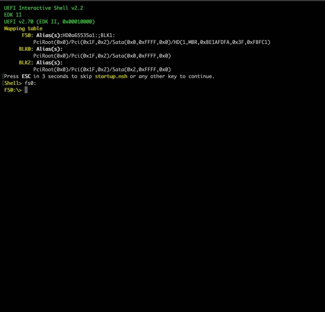
Figure 2: UEFI shell CLI, accessed after selecting the EFI shell as the boot device during system power on.
From either an IBV-specific management console or the EFI shell, your next step to dumping the flash is disabling Secure Boot so that you can plug in your USB preloaded with Chipsec and boot into the UEFI shell. Depending on the device, accomplishing this “boot-to-Chipsec USB” goal may also require adjusting BIOS settings to enable booting from a USB or changing the boot order. After configuring the settings correctly, you’ll power off the device, plug in your Chipsec USB, power on the device, and, if all goes correctly, land in the UEFI shell. From here, you can use one of the Chipsec utilities to dump the firmware image directly from the SPI flash chip.
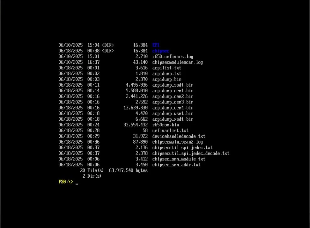
Figure 3: UEFI shell on after booting to USB device loaded with Chipsec. Directory content listings show two primary directories (“Chipsec” & “EFI”), while the remaining listings show previously completed Chipsec scan results saved to the USB.
This approach offers a major benefit: Once you have your flash dump, you can use Chipsec’s built-in utilities to further explore the UEFI BIOS. Running python.efi chipsec_main.py will trigger all built-in Chipsec modules to be run against the target and output a report containing general information about the chipset and the firmware. It also reports whether the UEFI BIOS has any common security misconfigurations or vulnerabilities because it includes targeted scripts designed to identify particular vulnerabilities. For instance, cr4sh’s s3bootscript module [7], can determine whether the target device is susceptible to the S3 Resume Boot Script vulnerability, famously discovered by Rafal Wojtczuk and Corey Kallenberg [6].
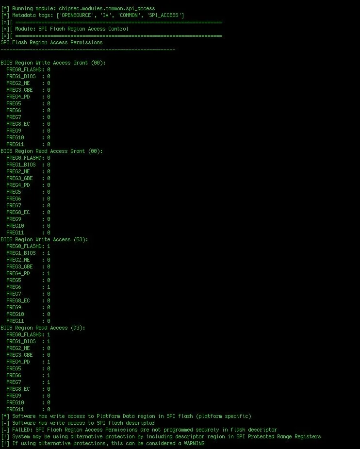
Figure 4: Example snippet of output report generated from Chipsec after running 'python.efi chipsec_main.py' against a target device.
Working with locked down devices requires a different approach. You’ll need to extract the firmware directly from the flash chip. It is important to note that you can unrecoverably brick your board when you attempt to extract the UEFI firmware from SPI flash in this way, so proceed with caution. I won’t detail the specific procedure for dumping a SPI flash chip here, as numerous resources already cover this core hardware hacking skill (see references 1 and 5). Broadly speaking, however, here’s a quick overview of the process:
Open up the device.
Identify the SPI flash chip on the main board (if multiple, pick one chip to start with, then rinse and repeat steps 3-4).
Connect to it with a SPI programmer (e.g., Hydrabus).
Dump the flash chip over SPI. Bada-bing.
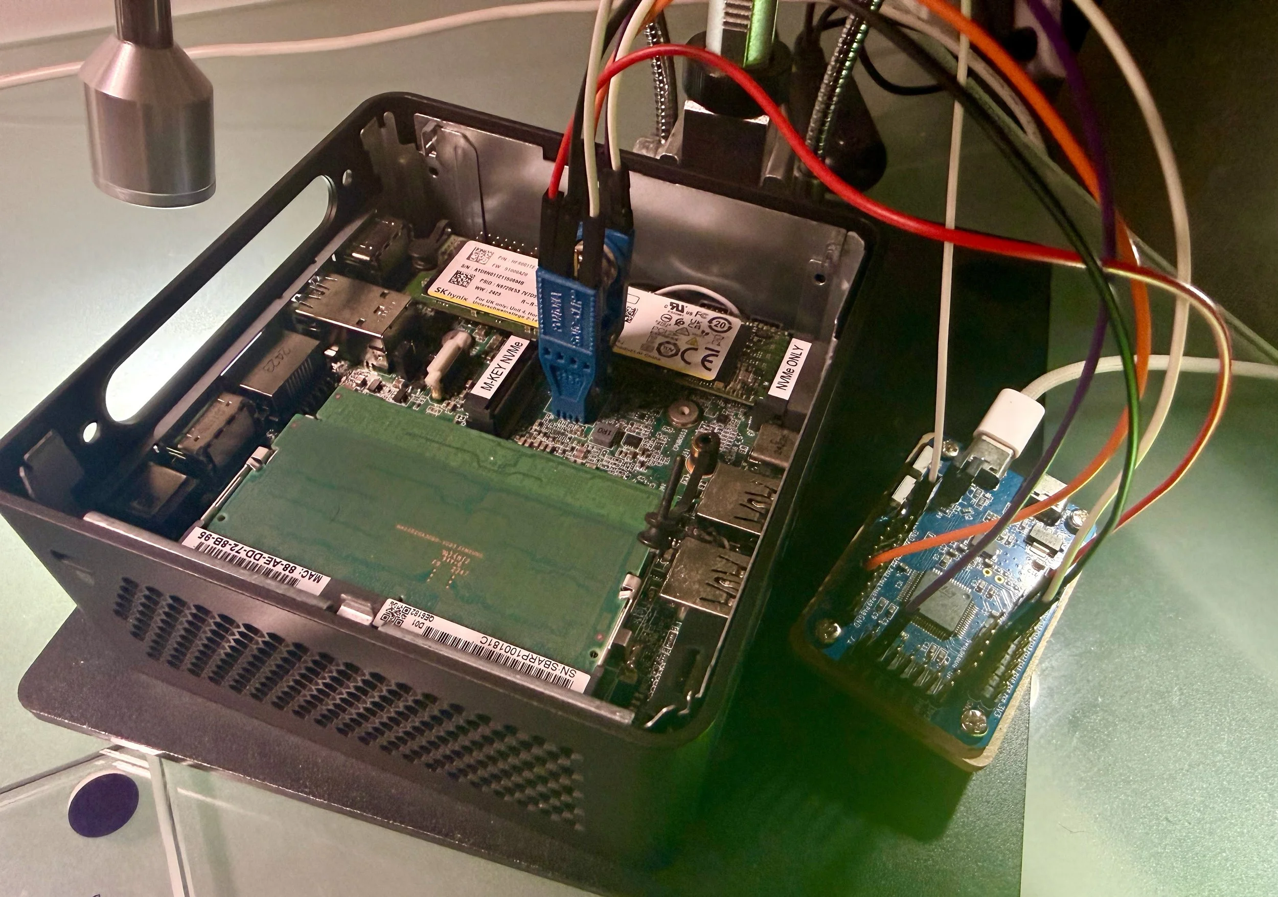
Figure 5: Dumping the SPI flash chip of a target device using a Hydrabus and flashrom; after the flash has been dumped we can extract the UEFI/BIOS and the EFI drivers.
Other techniques for extraction of the firmware image from flash are detailed in reference 1.
Now that we have our basic lab set up and our UEFI BIOS firmware image acquired, we can move on to binary analysis of the flash dump. Next time, we’ll continue this journey by delving into UEFI reverse engineering and binary analysis of our target UEFI image.
Credits
Prepared by: Nika Korchok Wakulich
LinkedIn: (https://www.linkedin.com/in/nika-kw/)
References
[1]“Rootkits and Bootkits: Reversing Modern Malware and Next Generation Threats,”by Alex Matrosov, Eugene Rodionov, and Sergey Bratus, 2019, https://nostarch.com/rootkits
[2] Building reliable SMM backdoor for UEFI based platforms, cr4sh, 5 July 2015, https://web.archive.org/web/20200103113737/http://blog.cr4.sh/2015/07/building-reliable-smm-backdoor-for-uefi.html
[3] (OST2) Architecture 4021: Introductory UEFI, https://ost2.fyi/Arch4021
[4] (OST2) Architecture 4001: x86-64 Intel Firmware Attack & Defense, https://ost2.fyi/Arch4001
[5] (OST2) Hardware 1101: Intel SPI Analysis, https://ost2.fyi/HW1101
[6] “Attacking UEFI Boot Script,” Rafal Wojtczuk and Corey Kallenberg, 2015, https://bromiumlabs.wordpress.com/wp-content/uploads/2015/01/venamis_whitepaper.pdf
[7] “UEFI_boot_script_expl,” cr4sh, 2015, https://github.com/Cr4sh/UEFI_boot_script_expl